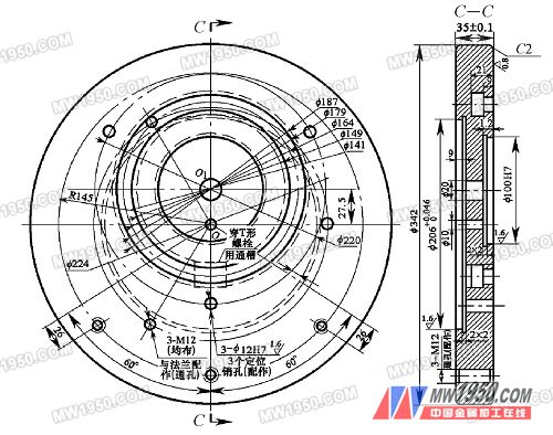
One-time installation of the multi-hole turning jig (2)
1 fixed disk installation Remove the chuck mounted on the lathe and secure the mounting plate to the lathe flange with three M12 hex head bolts. 2 positioning plate installation The positioning plate is directly placed on the fixed plate, and then the positioning plate is fastened by the M14 nut, and then the weight block and the two M14 bolts for the two clamping valve bodies are sequentially installed and fastened. 3 clamping valve body parts Install the body parts on the two locating pins and clamp the body parts with two M14 nuts (as shown in Figure 2). 4 boring valve body hole 1 (see Figure 1) When the circular hole 1 is turned into coincidence with the machine tool spindle (Note: the positioner automatically enters the positioning hole at this time to position the indexing mechanism), and the positioning plate is tightened by T-slots and bolts. The processing of the circular hole 1 is: reaming with a twist drill to 21 mm → rough boring → fine boring to the specified requirements of the pattern. 5 indexing division Loosen the three M14T bolts and nuts, pull out the indexing positioner, and the positioning plate indexing mechanism and the valve body parts rotate around the positioning circular boss. When the round hole 2 of the valve body part is rotated to coincide with the axis of the machine tool spindle, the positioner automatically enters the positioning hole to position the indexing mechanism, and then tighten the three M14 nuts with tools. The processing of the circular hole 2 is the same as the method of processing the circular hole 1. 6 re-indexing The circular hole 3 is machined in 45 steps. 7 remove the valve body Loosen the M14 nuts of the two compression valve body parts, remove the processed valve body parts, install the valve body parts to be machined to the original position of the fixture, and then repeat the above process to boring the inner hole. Since the center of rotation of the positioning disc does not coincide with the center of rotation of the fixed disc (eccentricity 27.5 mm), in order to eliminate the unbalance of the rotation and reduce the influence of unfavorable factors such as vibration on the processing quality of the valve body, the fixture is designed with balancing measures. A weight is mounted at a position opposite to the positioning plate at the fixed disk. 4. Fixture design and manufacturing points (1) Design and processing of fixed disk (shown in Figure 3) Figure 3 fixed disk 1 size setting is based on the size of the workpiece, the position of the T-slot and the indexing pin hole and the size of the positioning plate to determine its external dimensions. 2 materials used HT200 cast iron. 3 processing. a. Processing the first side with a chuck to clamp the outer circumference of the cast iron blank, correct the outer end surface of the blank, flatten the end face to meet the requirements of the drawing, drill a 10 mm through hole, and turn the 206H7mm and the deep 9mm with the lathe flange. hole. b. Three M12 internal threads that are machined to the lathe flange will be solid The fixing plate is matched with the flange, and then three M12 threaded bottom holes are drilled, and three M12 internal threads are tapped. c. Machining the second side The M12 hex head bolts are used to fasten the fixing plate to the flange, and the outer circle and the end surface are required to be turned according to the drawing. d. Turn the T-slot to install and align the fixed plate. It is required to drill a 20 mm through hole according to the pattern, then boring 100H7 mm, deep 12 mm counterbore, and finally turning the T-shaped groove to meet the drawing requirements. e. Machining the M12 internal thread for the installation of the weights on the digital drilling machine. According to the drawing, three M12 threaded bottom holes for the weights are drilled, and three M12 internal threads are tapped. f. Milling notch A 20 mm wide, 28 mm long notch is milled on the back of the T-slot to penetrate the M14 T-bolt. g. The grinding plane grinds the upper surface with the end face that matches the flange (the entire surface is flattened). Previous page next page
(3) How to use the fixture