CAXA electronic board and entity design simulation application
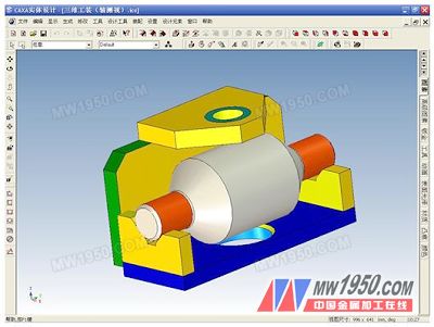
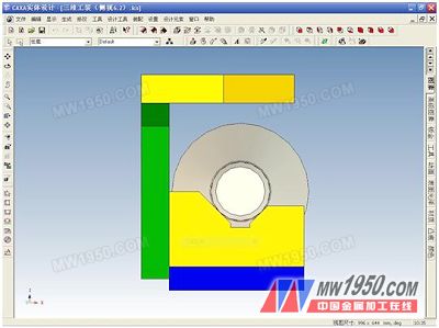
Abstract: This article introduces the working principle of a batch export order called a rotary yoke (the part is a steel casting). After casting, the finishing belt is drilled and the parts are small, and the dimensions are shown in the following figure <1>. Figure <1> Rotary yoke In the figure, Φ20.4 requires a vertical positioning reference with a 2-Φ25.4 cylinder, and the horizontal length is 137.2. To do this, design a drilling tool. The initial idea of ​​the tooling is that the two V-shaped seat card 2—Φ25.4 short cylindrical surface, a fixed drill sleeve is arranged above the middle hole, and the length alignment can be solved by the two-claw linkage self-centering chuck. After conception, the tooling is shown in the following figure <2>. Figure <2> Tooling When designing the above tooling, we found that the height distance "C" value of the hole fixing drill sleeve in the tooling was difficult to determine. The distance "C" should make the working length of the Φ20.4 drill bit more suitable, that is, it is convenient to take out and put the workpiece by hand from the tooling, and the number of sharpening of the drill bit should be as much as possible. The long drill pipe has poor rigidity and cannot be used after a few times of sharp grinding. For this problem, we can try to simulate and demonstrate through CAXA electronic board 2007R3 and entity design 2007. First, CAXA electronic board The tooling drawing is drawn 1:1 with an electronic drawing board, as shown in Fig. <2>. In the point capture state is "Navigation", use the left button to select two concentric circles Φ25.4, Φ50.8, right-click shortcut menu to select "Copy selection to", the first point is selected in the lower circle quadrant point "O" (The lowest point of the small circle) Move the mouse to appear two concentric circles moving (set to "non-orthogonal" shape), at this point to simulate the movement of the workpiece when it is taken out in the tooling, even if the cutting point "M" is along the slope side Move to the small circle selected point (the first positioning point "O") just beyond the V-shaped groove, as shown in <2> copy to the position of the "O'" point, then give the appropriate A, B values, A suitable "C" value can be determined to determine the other dimensions of the tooling. Second, CAXA entity design In the physical design, a three-dimensional drawing of the tooling is drawn 1:1, and the steps are as follows: 1, the workpiece - one of the methods is to create a sketch, and then get through the rotation command; 2, tooling - one of the methods is to drag and drop pixels for combined design; 3. Place the workpiece into the tooling V-groove through the three-dimensional ball. In this way, the tooling axonometric drawing of Fig. <3> and the tooling side view of Fig. <4> are obtained. Figure <3> Axonometric diagram In the design of the tooling entity, we intuitively found that the height "C" can be further reduced, that is, the height of the right shoulder of the V-groove (side view, the direction in which the workpiece is taken out) is lowered to a slightly higher cut point "M". (Figure 2). In the isometric view <3>, the three-dimensional ball is loaded on the bottom plate, and the edit distance can give a suitable "A" value, as shown in Fig. <5>. Figure <4> Side view Figure <5> Editing the distance between the bottom plate and the workpiece circle "A" For the distance "B" value, we can move the workpiece to the right shoulder of the V-shaped groove through the three-dimensional ball, "disposed", as shown in Figure <6>, then use the three-dimensional ball on the top plate, such as editing "A" The value is the same to determine the appropriate "B" value. Figure <6> Place the workpiece on the right shoulder of the V-groove Next page