Application of Coordinate Measuring Machine in Coaxiality Measurement (2)
2.2 Straightness method Measure the circle of multiple cross-sections on the measured element and the reference element, and then select these circles to construct a 3D line with a coaxiality approximately twice the straightness. The collected circle is best measured for its full circle. If it is measured on a sector, the deviation calculated by the measurement software may be large. It can be seen from Table 1 that if a single hole is used as the reference axis, the evaluation result greatly exceeds the drawing requirements, and the results evaluated by the common axis method and the straightness method more comprehensively reflect the situation within the measured range. Previous page
2.3 The distance method is about twice the maximum distance between the measured element and the axis of the reference element. To calculate the maximum distance between the measured element and the reference element, use the relationship and multiply it by 2. The distance method is calculated by projecting it onto a plane when calculating the maximum distance, so this plane is better perpendicular to the axis used as the reference. This situation is more suitable for measuring concentricity.
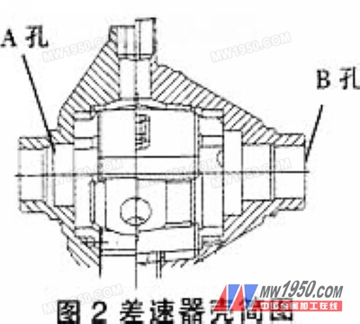
3. Practical application Now take the EATON differential case as an example: According to the drawings, the coaxiality of the inner hole of the bearing at both ends of the differential case is φ0.05 mm. If the coaxiality of the holes at both ends is not good, it will affect half. The assembly of the shaft and the gear causes the gear to rotate unsatisfactory, so it is necessary to accurately measure the coaxiality of the differential case. The schematic diagram of the differential case is shown in 2. Table 1 exemplifies the measurement data of the coaxiality. The distance method does not apply to the workpiece, so this is not an example. 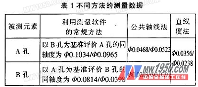
4. Conclusion In the actual measurement, the measurement of coaxiality is affected by many aspects. The operator's own quality and understanding of the drawing process requirements are different; the measuring error of the measuring machine, the error of the probe itself; the processing state of the workpiece, the surface roughness; the selection of the detection method, the placement of the workpiece, the combination of the probe; the external environment Etc., for example, the temperature, humidity, etc. between the tests will bring a certain error to the measurement. Therefore, in practical applications, we should consider more than the above factors.