Application of CAXA solid design in hydraulic manifold design (Figure)
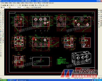
Abstract : This paper introduces the application of 3D design of integrated blocks in hydraulic system in CAXA physical design to improve design efficiency, visualization and reliability. Abstract: Introduced in the hydraulic system the integrated block in the CAXA entity design three dimensional design application, enhances the design the efficiency, the visualization and the reliability. introduction The high integration of modern hydraulic systems is developing rapidly, especially in the application of key components such as manifolds. In order to meet the complex and precise design requirements, a large number of computer-aided design platforms with three-dimensional design are adopted. The blocks of the integrated block are made of mature materials and processes such as steel and surface electroless nickel plating, which have the advantages of long service life and surface corrosion resistance. In order to make better use of its function, it is necessary to reasonably arrange the position and spacing of the holes, especially in the case of high integration, which fully demonstrates the superiority of the three-dimensional design. CAXA Entity Design is a three-dimensional design software with full-featured integration and integration. It has the advantages of easy learning, easy use, rapid innovation, and compatible synergy. Especially in the software, "3D ball", "smart capture" and "smart element library" The functions of “drag and drop operation†are simple, fast, convenient and flexible, which can greatly improve the work efficiency of designers. This software was used to draw 3D manifolds on the hydraulic system of Huaxin 36MN steel extrusion machine project, which fully verified the advantages of CAXA entity design software in integrated block design and application. 1. Design concept and specification of integrated block In the design process of the integrated block, one design concept to be followed is to maximize the arrangement of the hydraulic components and optimize the system performance with the minimization of the weight of the integrated block. In the context of rising raw material prices, the design process must consider maximizing economic benefits at the lowest cost. Of course, the design is to save as much material and cost as possible while meeting design requirements and functions. The design specification of the integrated block involves several aspects: including the rationality of the overall layout, meeting the safety requirements of the equipment and the piping direction; paying attention to the safety spacing of the oil passages, preventing the spacing of the cross-connections from being too small; paying attention to the safety of the hydraulic components Features to prevent mutual interference. 2, the physical design of the integrated block The following is an example of drawing an integrated block entity to introduce the design method and usage characteristics of the CAXA entity. Open CAXA entity design software, we can see that there are many "smart elements" in the "design element library" on the right side of the interface, such as cuboids, cylinders, fasteners, etc., which can be very convenient in the design process. Call these "smart pixels" to improve our design efficiency. The shape of the integrated block is generally rectangular, so directly select the "cuboid" to drag and drop into the drawing environment to form a rectangular entity. Select "Edit Bounding Box" to quickly modify the dimensions of this rectangular solid, and then you can create various integrated blocks on the rectangular solid according to the schematic requirements to generate various oil passages. Here's how to create two holes: the first is by selecting "Set Count the element library "→" tool, drag the "custom hole" to the reference point on the surface of the solid, and create the required inner hole by setting different detailed parameters in the pop-up "custom hole" dialog box; The second method is to generate holes of different diameters and depths (such as insert holes) by rotating the features. The specific step is to select the "rotation feature" on the toolbar, select a "reference point" on the entity, and "rotate the feature". In the "Wizard" dialog box, select "Dim", the rest of the default settings can be, click "Finish" after the surface of the entity appears a grid plane, and then draw through the "2D drawing" and "2D editing" toolbar below the window The cross-sectional profile of the required hole, and then click “Finish Selectionâ€, the physical characteristics of the hole appear. Of course, the holes generated by the two methods can be modified by changing the basic parameters of the “custom hole†and “edit sketch sectionâ€. Dimensional features. After the hole is generated, the final position of the feature hole is determined by rotating the three-dimensional ball to rotate, translate, copy, array, and mirror. After percent, also basically completed the basic design of the manifold of Figure 1 is a three-dimensional solid graphics complete the manifold has been drawn. Figure 1 3D graphics of the integrated block drawn by the CAXA entity design 3, the integration block rendering test After the integration block is drawn, in order to quickly, conveniently and intuitively observe the through-hole relationship of the internal holes of the integrated block, it can be realized by the "section" and "surface gloss" functions of the CAXA entity software. Suppose you want to display the internal condition of any section of the manifold. You can select different section types by “Modify†→ “Sectionâ€, and then click any point of the plane you want to observe. The section graph of the integrated block is displayed. You can directly drag the section to observe any section in a certain direction. If you want to observe the relationship between the internal channels of the integrated block as a whole, you can first select the integrated block entity in the "face point" state, and then drag the "glass" to the solid surface. Even if it is in a transparent state, you can clearly observe it. All the holes inside the body, check the position, spacing and intersection of the holes from any angle. Figure 2 shows the effect of the integrated block after rendering, so that the relationship of the internal holes can be clearly seen. If you want the holes to be more easily identifiable, you can add different colors to different holes to form a strong chromatic aberration. Drag the different colors to the inner hole surface by “Design Element Library†→ “Surface Gloss†or “Colorâ€. The color you want. Figure 2 integrated block rendering renderings 4, the animation design of the integrated block In the sample of hydraulic components, we can often see the effect graphics of the explosion map. In fact, these effects are easy to implement in the CAXA entity software. In addition, the CAXA entity software can also use the smart motion to convert the static explosion map. It is animated and played as a demo animation for the user to understand the assembly effect of the integrated block more intuitively and vividly. After the integrated block is drawn, the generated hydraulic assembly components can be used to generate simple animation breaks through the “smart animation guideâ€, or the “smart animation editor†can be used to accurately set the movement process and time. The purpose of complex animation. 5, CAXA entity software application skills (1) Feature combination, establishing a common library of hydraulic element features. In the physical drawing process, standard hole shapes of many standard components are often generated. These holes are relatively fixed in size and used frequently. Therefore, these standard hole shape features can be stored in the new feature library in the Design Element Library. In, it is convenient to call again. The new feature library is selected from "Design Element" → "New". At this time, a new library is added to the design element library, such as renamed to "Hydraulic Element", so that multiple feature holes can be generated (such as The bottom holes of the 10-way valve are combined into one feature element and stored in the new "Hydraulic Element" library. Feature merging usually has two methods: the first one is to select multiple feature holes, select “Design Tool†→ “Combination Featureâ€, and then combine the multi-feature elements into one feature element, then drag it directly into “ The hydraulic element can be stored in the library and can be recalled at any time after saving. The second method is simpler, just drag the selected feature holes directly into the "Hydraulic Elements" library. (2) Application skills of positioning anchors for feature elements (such as holes). Suppose you want to change the size of the drawn integrated block. If the state of the anchor of the feature element is not set properly in the previous period, the feature hole of the solid surface may not change with the change of the integrated block, resulting in unnecessary errors. occur. In order to avoid such a situation, after each feature hole is generated, the positioning anchor of the hole is clicked to activate the three-dimensional ball, and the rotating long-axis of the positioning anchor is directed to the axial direction of the hole by rotating the three-dimensional ball, and then the three-dimensional ball state is exited. Select the anchor of the hole again, right click and select "attach to the surface". With such a setting of the positioning anchor, the feature hole always adheres to the surface movement regardless of the change in the size of the body. (3) Application skills of Boolean operations in the integration block. In order to more accurately and intuitively observe the through-hole relationship of the inner hole of the integrated block, in addition to the transparent rendering method, there is another method: that is, the "Boolean operation" method is used to display the internal relationship of the internal channel through the entity. This can be more accurate, more intuitive and more careful observation. The steps are as follows: 1 Drag and drop a box in the Design Element Library. 2 Change the shape of the cuboid to match the size of the resulting integrated block outline. 3 Select both entities at the same time, select “Design Tool†→ “Subtractionâ€, which will generate the effect shown in Figure 3. At this time, only the physical features of the hole appear in the figure. Figure 3 Effect diagram of the integrated block after Boolean operation 6, the drawing of the drawing of the integrated block (1) Drawing engineering drawings in CAXA entity software The 2D drawing function of the CAXA Entity Software is primarily used to create 2D drawings associated with 3D parts or assemblies. The steps for generating the drawing in the physical software are as follows: 1 Select “File†→ “New†→ “Draw†to enter the drawing environment. 2 Select “Generate†→ “View†→ “Standard View†and select the view to be expressed in the “Standard View†dialog box to generate. 3 Use the 2D drawing function in the CAXA entity software to edit the drawing. (2) Drawing engineering drawings in CAXA electronic drawing board The steps for generating the drawing in the CAXA electronic drawing board are as follows: 1 Select “Tools†→ “View Management†→ “Read in Standard Viewâ€, select the CAXA entity graphic file that has been drawn, in the “Standard View Output†dialog box. Select the view you want to express for generation. 2 Select “Tools†→ “View Management†→ “Generate Section Viewâ€, select the section position and direction, and generate the required section view to express the diameter and depth of the internal tunnel. 3 When the CAXA entity graphic file changes, the generated 2D drawing can also be changed in real time by selecting “Tools†→ “View Management†→ “View Updateâ€. 4 Use the 2D drawing function to edit the drawing to generate the final drawing. Figure 4 shows the engineering diagram generated by the integrated block entity through the CAXA electronic board. Figure 4 Drawings generated by the integrated block entity 7, the conclusion In the modern manufacturing industry, the scientific management system, the rigorous process, and the advanced design software and processing equipment are the solid foundation for the completion of high-quality products. As an important component of the fluid system, the integrated block has strong interactivity and visibility with CAXA entity software, which not only improves design efficiency and product reliability, but also is easy to operate, and has a very high level of design for improving the integrated block. Great help.